Instruction PDF s
Generic Assembly Instructions
Locking Spring Demonstration (also included in Generic Assembly Instructions)
Hinge set instructions
Panel Clip Demonstration
Step One – Instructions
Abstracta is based upon steel tubes and metal or polymer connectors. The easiest way to begin assembly is to simplify each section. All units are assembled by building “bones” first, then by building either horizontal or vertical “ladders,” described below.
With your specific unit in mind, decide if you want to build the horizontal or the vertical sections first. Do not attempt to build both simultaneously. This will make assembly far more difficult. Note: Use a Nylon-ended hammer for best results.
If you find that you have placed a connector or tube incorrectly and need to remove it, see the “Disconnect Tool” and “Extractor Rod” below.
Contact your sales representative with any questions.
Step Two – Abstracta “Bones”
A single tube with the inserted connectors on each end is considered a “bone.”
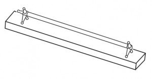

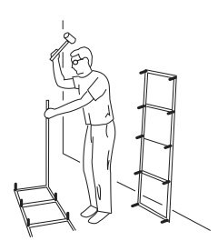
To assemble a bone, insert connectors into a tube making sure the connectors are symmetric to each other (the connectors are represented by color coding on unit specific instructions, which are supplied with stock and custom units). This is shown with the piece of wood in the diagram. Partially tap connectors into tubes. Once you have confirmed that both ends are correctly placed, hammer until connector is flush with the tube.
Follow this procedure of making “bones” throughout assembly.
For every square section of an Abstracta unit only the two tubes that make the depth of the square are bones. The intermittent tubes will be added later.
Step Three – Abstracta “Ladders”
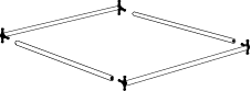
 Once all of the bones for a section have been assembled, lay them out parallel to each other and insert the intermittent tubes. These are ladders. Fully assemble each ladder referencing the color coded instructions for accurate connector placement. If your design is a tower, your horizontal ladder will be as simple as a square.
Step Four
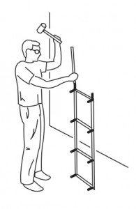
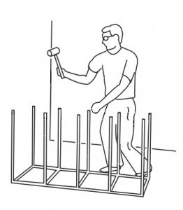
When all ladders are complete, lay the beginning section on the floor and hammer in the first set of vertical tubes. If your unit includes legs (short tubes on the bottom) do not add these yet.
Once you confirm that everything is in place make sure tubes are flush to connectors. There should be no space or gap between the tube and the connector.
Step Five
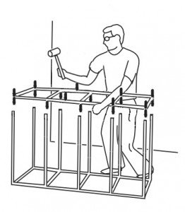 Place the next ladder on the open tubes. Gently tap in the ladder slightly by about 1/4″ to insert the connector arms on the ladder into the first set of tubes. Based upon the length of the ladder it is often easier to insert the connections into groupings or pairs.
Once all connectors from the ladder are in place, hammer all of the connectors half way as some may not remain in place. Go over them once more, hammering them in all the way, making them flush with the tubes. This progression is to avoid stress on the connector arms.
Step Six
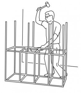 Hammer in the second set of vertical tubes and then the next ladder repeating the same procedure until finished.
Step Seven – Legs
If your unit has legs, confirm everything is correctly in place and tight on the entire unit before adding them. Place the legs on last and hammer them so they are flush. The legs are basically permanent as they are shorter than the disconnect tool itself and not recommended for removal.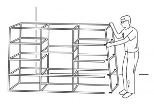
Once assembly is complete push the plastic glides (506) or hammer Adjustable Legs (3705) into the short tubes. Typically all open tubes would have plastic glides or Adjustable legs. Glides and Legs are not designed to be removed. With plastic Glides, hammering the unit once they are in place may cause damage to glides. Therefore it is important that this is a last step in the construction of your unit.
Caution
Before moving the display or placing shelving or graphics, make sure that all tubes are hammered completely onto the connector arms. Leave no space between the tube and the shoulder of the connector arms. Due to the tight fit the tube ends can scrape a bit of finish off the connector shoulders. Remove the small splinters with the flat end of your nylon mallet. Bare hands are not recommended as the splinters may be sharp.
Step Eight – Shelving Placement
When the unit assembly is complete and the structure is upright, carry the unit to the proper place. Attach the asymmetrical brackets (620/625) and any other accessories before installing shelving. The bumpers (012) are placed in the center of the shelf brackets. These are optional, but they give the glass a more solid setting and provide a more secure fit for shelving.
Step Nine – Panel / Adjustable Shelf Clips
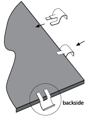
Panel clips (728A/728B) should be attached to vertical panels before attaching them to the tubes. A minimum of one clip per side is recommended. Longer lengths or more flexible substrates may require more clips. Put pressure on both sides of panel when attaching.


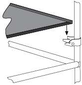
If you are attaching adjustable shelf brackets (527) make sure to measure placement on the vertical (upright) tubes for all four brackets so that the shelf is level. The 527 clips face the center of the shelf with the straight arms on the bottom and the flared arms on the top. To assure proper shelving fit, do not tighten the clips all the way until the shelf or panel is accurately in place.

Troubleshooting
Both versions of the connectors are durable, the zinc casting (Original Connectors) or polymer composite (Cubitz® Connectors), and we recommend assembling them with a nylon mallet. Disassembling units with the mallet will break connectors and is not recommended – for disassembly see “Disconnect Tool” below.
If a connector end has broken off at the base of the joint and is stuck in the tube, it is preferable to knock it out from the opposite end with our Extractor Rod, a 1/4″ or 5/16″ diameter steel rod that is longer than the tube. The 36″ Extractor Rod (EX-ABS) is recommended for this. See the “Abstracta Disassemble” video in “LEARN”.
If the opposite end of the tube with a broken connector is attached to another connector, try to knock the broken arm far enough into the tube with a screwdriver and mallet so that a replacement connector can then fit in its place.
Additional Information
Curved Tube Tips
Hold curved tube in one hand. Place connector in tube and using mallet, hammer connector into tube. Make sure to attach these to the connections early in the construction.
If two curved tubes are being connected in the design, hold one curved tube in hand. Using a wood block as a brace, hammer the end of second tube to make one half circle.
Offset Tube Connections Tip
When hammering tubes in “offset sections” – sections where the connection is not continuous on the other side – use a wood block for support. This minimizes stress to other connectors and tubes.
Locking Springs
Locking springs are NOT include with units (unless ordered) and are not required for assembly. They are for permanent displays or very loose connections, and may be purchased separately. (Note: not available for Cubitz® connectors). See the video, “Abstracta Table Assembly” under “LEARN” for a demonstration of the Locking Spring.
Locking Spring Instructions (for metal connectors only) :
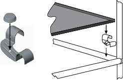
1. Place locking spring into the grooves on the head of the connector.
2. Align tube over the connector head. Hold tube firmly against spring.
3. Hammer tube onto the connector using a nylon or rawhide hammer.
Disassembly and the Disconnect Tool
We strongly recommend using our Disconnect Tool (915) for taking Abstracta apart. This tool allows for an even distribution of pressure on the connection. Using the mallet or a hammer to disassemble increases the risk of breaking connectors. See the “Abstracta Disassemble” video in “LEARN”.
To use the tool, firmly grasp the tube and position it in the channel of the Disconnect Tool with the larger end of the tool facing the connector. Rotate the tool to contact the flat end of the tool against one or more connector arms. Strike the connector arms with the tool until loose. Point the tube down so the connector will not hit anything when disconnected.